Automated Levitation and Manipulation of Droplets
December 9, 2016
Demo
DOD and Gantry operationd durring Automated Droplet Testing
Exparamental Results:
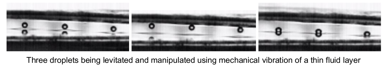
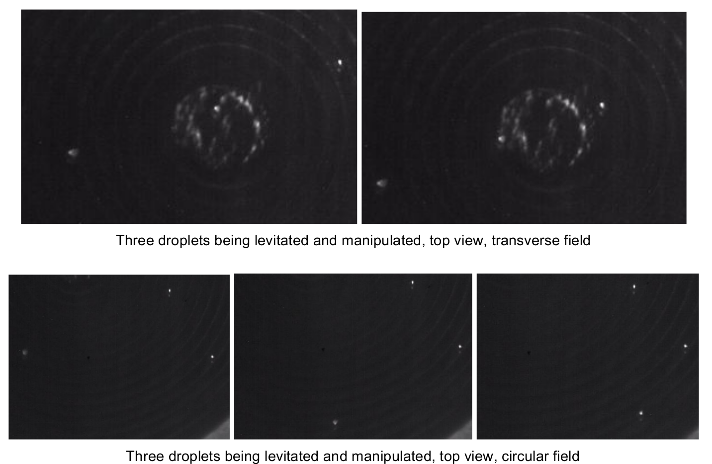
3 Dropltes moving in a transverse field
3 Droplets maving in a circular field
Project Overview
Effective control of small liquid volumes drives enabling technology in many important fields that are vital to the well being and advancement of society including medicine, chemistry, and biology; examples include screening for drug efficacy and interaction, ecological and biological contaminants, and gene expression.
This project’s focus is on levitation and manipulation of small liquid droplets using vibration. Vertical vibration of a flat surface will be used to suspend droplets above the surface on a thin layer of air, while horizontal vibrations will move drops across the surface. The work relies on the closely related field of frictional manipulation, and on the laboratory’s unique vibratory platform (PPOD) that is capable of generating arbitrary programmable 6-degree-of-freedom vibration patterns.
Previous students have contributed significant work to this project already. The development of the PPOD and the Droplet On Demand (DOD) generator were both contributions from past researchers. My focus in this project is primarily to develop a two dimension positioning system for the DOD generator and further development and refinement of the automated droplet testing procedures.
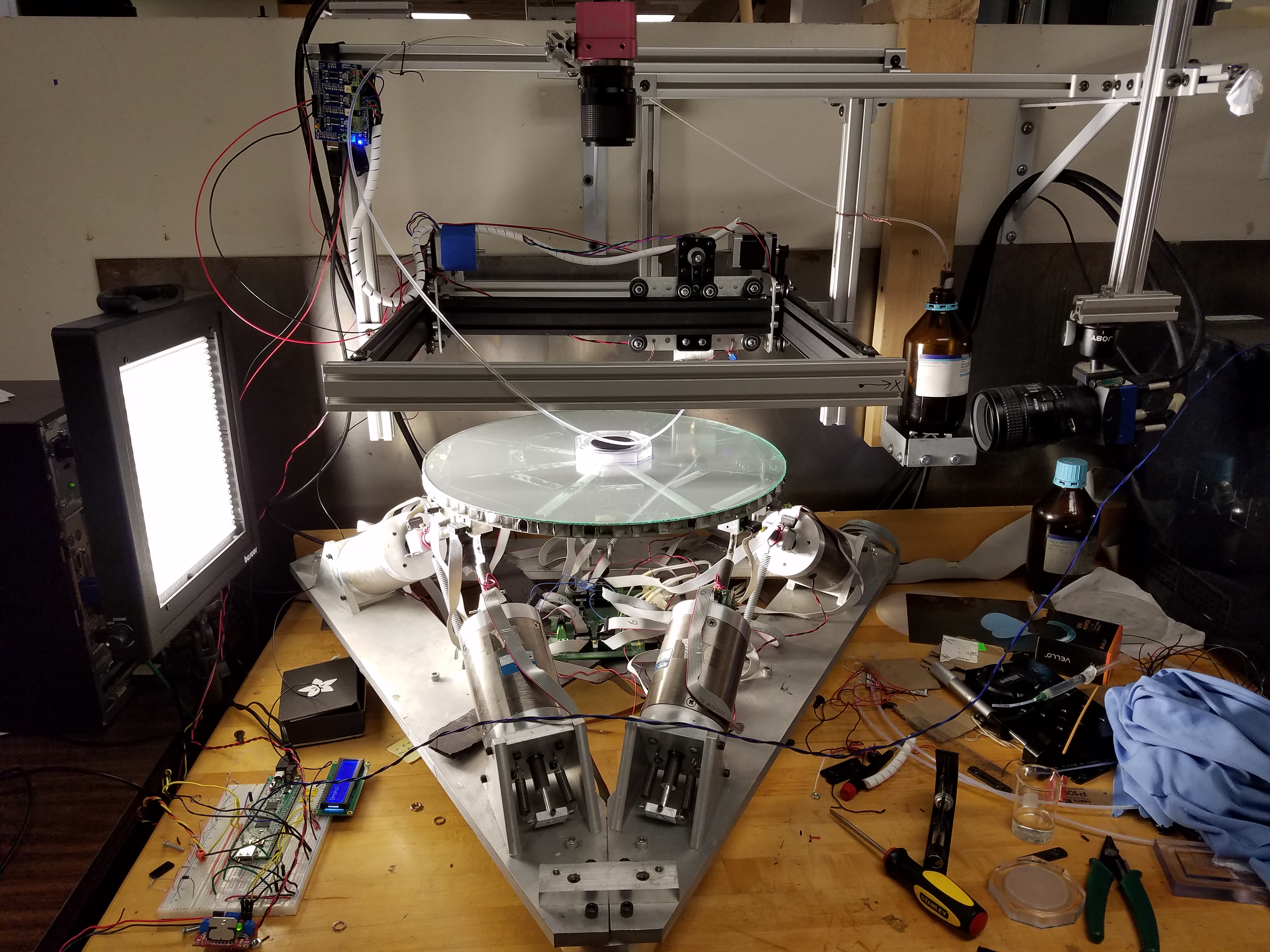
Component Description
This section overviews the various components of the experimental setup, including pictures and descriptions of code operation and equipment behavior.
PPOD
Six degree of freedom vibration table developed to manipulate small planar masses. The device consists of six linear actuators coupled to a rigid plate whose movement is sensed by embedded accelerometers and controlled by a computer.
-
Can specify different vibration frequencies for vertical motion, horizontal motion in two directions, and rotations about 3 axis
-
Vertical vibrations used to bounce droplets
-
Horizontal vibration used to apply horizontal acceleration to droplets
TestingFile.txt (Windows)
Text file used to set experimental parameters. Each line represents an experiment and can performs certain actions: make a droplet at a specific coordinate, change the PPOD vibration frequencies, take a video on both cameras. Multiple such experiments can be performed in quick succession automatically. Additionally, these lines can be used to set up more intricate conditions, such as creating multiple droplets at different locations then taking extended, high speed videos of them.
-
Each line of the text file represents a single experiment run
-
Set up using a predefined parameter string that other programs parce
-
Controls behavior of PPOD, DOD gantry and cameras
AreaFreeRun_TrackCam_TestingFile.cpp (Windows) - SDK Runtime 5.1
Program that controls the majority of the timing of the automated droplet testing. This program communicates with the Linux and PPOD computers, as well as the PIC32 and Arduino UNO microcontrollers, reads testing parameters from the text file, and captures the video recorded by the TrackCam (overhead) camera.
-
Reads set of testing parameters from a text file called ‘TestingFile.txt’
-
Initializes serial communication port for PIC32, Arduino Uno, and Winsock (UDP messages)
-
Performs Homing cycle on the DOD Gantry and moves it to default position (center of PPOD)
-
Initializes frame grabber board properties for later use when opening frame grabber
-
Local variables definition
-
Check last four characters of argv[1] to ensure a .txt file was provided
-
Open text file, count the number of lines in text file (commented lines and testing lines), close text file
-
Reopen text file
-
Main loop controlling the automated testing
-
Read next non-commented line containing set of testing parameters
-
Determine if first parameter (IDENTIFIER) is loading a PPOD saved signal (S), or writing PPOD acceleration equations (E)
-
Share current testing parameters from GUI over to Linux computer via UDP comm
-
Open microEnable frame grabber (TrackCam) with certain properties
-
Memory allocation for framebuffer and frame numbers
-
Receive UDP datagram from Linux computer saying that it is ready to startcapturing the sequence avi
-
Move DOD to specified droplet location
-
Send UDP message to PPOD controller for modifying the shaking signals
-
Waits for UDP message from PPOD (containing error value) to be below a certain threshold value before continuing
-
Sends serial command to PIC to create droplet and generate ExSync triggers
-
If Cam_Move is True(1), move DOD out of camera frame
-
Receive framebuffer data from microEnable frame grabber and stores into buf[], as well as the current frame number
-
Write to avi file using VideoWriter - converts framebuffer data from buf[] into OpenCV Matrix (Mat)
-
Release OpenCV VideoWriter
-
Close frame grabber and free grabber resources
-
If PPOD_RESET is True(1), reset PPOD shaking signals to all {0}
-
Determine if there are more lines to be read at the end of text file, or at the end of the file -> update RunFlag
-
Send RunFlag to Linux via UDP comm, waits for UDP message receival
-
This has been commented out, but can be reinstated if necessary:
-
Send filename to Machine B (MATLAB) on the Linux computer to start the automated video analysis of both .avi files
-
Receive datagram back from Machine B (MATLAB) saying it has finished analyzing both .avi files
-
-
RunFlag determines whether there are more lines in text file for testing
-
If RunFlag == 1, restarts recording procedure at top of main loop
-
If RunFlag == 0, exits main loop
-
-
Close text file
-
Also commented out:
- Send datagram to Machine B (MATLAB) to tell MATLAB there are no more .avi files for analysis
-
Close serial port, Winsock, and UDP sockets
-
capture_avi_sequence.c (Linux)
This program primarily runs the frame grabber for the Mikrotron (side) camera. It communicates with the Windows machine via UDP messages to coordinate timing.
-
Loads format file (.fmt) to load for the camera (loads AOI, exposure time, triggering, frame buffer size, etc)
-
Main function of the code:
-
Blocking function call waits for UDP message from AreaFreeRun (Windows computer)
-
Reads in UDP message from Windows computer into local variables
-
Opens and initializes frame grabber resources
-
Right before starting to capture sequence avi, sends UDP message over to AreaFreeRun project to say it’s ready to start capturing sequence avi
-
Blocking function call waits for receiving NUMIMAGES frames from Mikrotron camera (unblocked when all frames captured)
-
OpenCV is used to convert the framebuffer data into Matrix (Mat) and writes to avi file using VideoWriter
-
Closes frame grabber resources
-
Waits for UDP message from AreaFreeRun project for Continue_Flag to see if capturing more than one sequence avi
-
If Continue_Flag == 1, restarts recording procedure (starts at blocking function call waiting for UDP message from Windows computer)
-
If Continue_Flag == 0, closes UDP sockets and exits program
-
slave_2_cameras_integer_multiple.c (PIC32)
This code is run on the PIC32 microcontroller and controls the creation and timing of the droplet in relation to the cameras and the PPOD. It generates the trigger signal the cameras use to take video frames.
-
Blocking function call waits for serial command from AreaFreeRun project
-
ISR for creating ExSync triggers automatically sets the prescaler and period register for both ISRs
-
RecordFlag is turned ON
-
When next PPOD reference signal is received (Change Notification ISR), TriggerFlag is turned ON, droplet created after DELAYTIME seconds
-
ExSync trigger ISR generates trigger signals, up to NUMIMAGES triggers
-
Mikrotron (side view camera) is recorded at FPS_Side fps for NUMIMAGES_Side frames
-
TrackCam (top view camera) is recorded at (FPS_Side/INTEGER_MULTIPLE) fps for (NUMIMAGES_Side/INTEGER_MULTIPLE) frames
-
Both ExSync triggers are started at the same time and last for the same time duration (assuming INTEGER MULTIPLE is actually an integer multiple of NUMIMAGES_Side: (NUMIMAGES_SIDE % INTEGER_MULTIPLE)==0
-
-
Once correct number of ExSync triggers have both been sent, turn TriggerFlag and RecordFlag OFF
-
Sleep for 2 seconds (helps in not creating 2 droplets)
-
Waits for next serial command to come in from AreaFreeRun project
-
Note: the USER button is attached to an ISR routine that creates a droplet with PULSETIME 900 us
-Once a serial command has been sent from AreaFreeRun with a new PULSETIME, the PULSETIME for USER button ISR is updated with the new value
PPOD_6D_Master_GUI.m (PPOD)
This is A GUI used to control the PPOD. The Windows machine sends test signals which this program runs on the PPOD. It returns an error value to the Windows computer and a reference signal to the PIC32 to coordinate the droplet timing with the vibration of the PPOD.
-
Once GUI has been opened:
-
Set frequency (if new frequency or anything has been moved on top of the PPOD, save new frequency response data - add frequencies button)
-
Modify anything else if relevant
-
Start controller (run button)
-
-
UDP signal control:
-
Code has been added in order to allow UDP control of the shaking signals (udpReceive.m and lines 63-67, 2120-2186, 2236-2238 in PPOD_6D_Master_GUI.m)
-
udpReceive.m: create UDP object with IP addresses and ports for Machine A (Windows) and Machine C (PPOD)
-
PPOD_6D_Master_GUI.m:
-
lines 63-67: call udpReceive.m with handles class, create DatagramReceivedFcn callback event, open UDP object
-
lines 2120-2186: callback function once UDP message has been received, setting the shaking signals to either acceleration signals or loading saved signal
-
lines 2236-2236: close and delete UDP object, clear memory reserved for IP addresses, ports, and UDP object (advised by MATLAB)
-
-
There are two options for controlling the shaking signals:
-
Acceleration signals filled out from GUI using Horiz_Ampl_X, Horiz_Ampl_Y, Phase, Vert_Ampl, Horiz_Alpha_X, Horiz_Alpha_Y, Vert_Alpha.
-
Load a saved signal from the SavedSignal list in the GUI
-
-
PPOD controller sends absolute value of error back over UDP each PPOD update
- After AreaFreeRun project sends UDP command to change signals, it waits until error below a threshold value before continuing
-
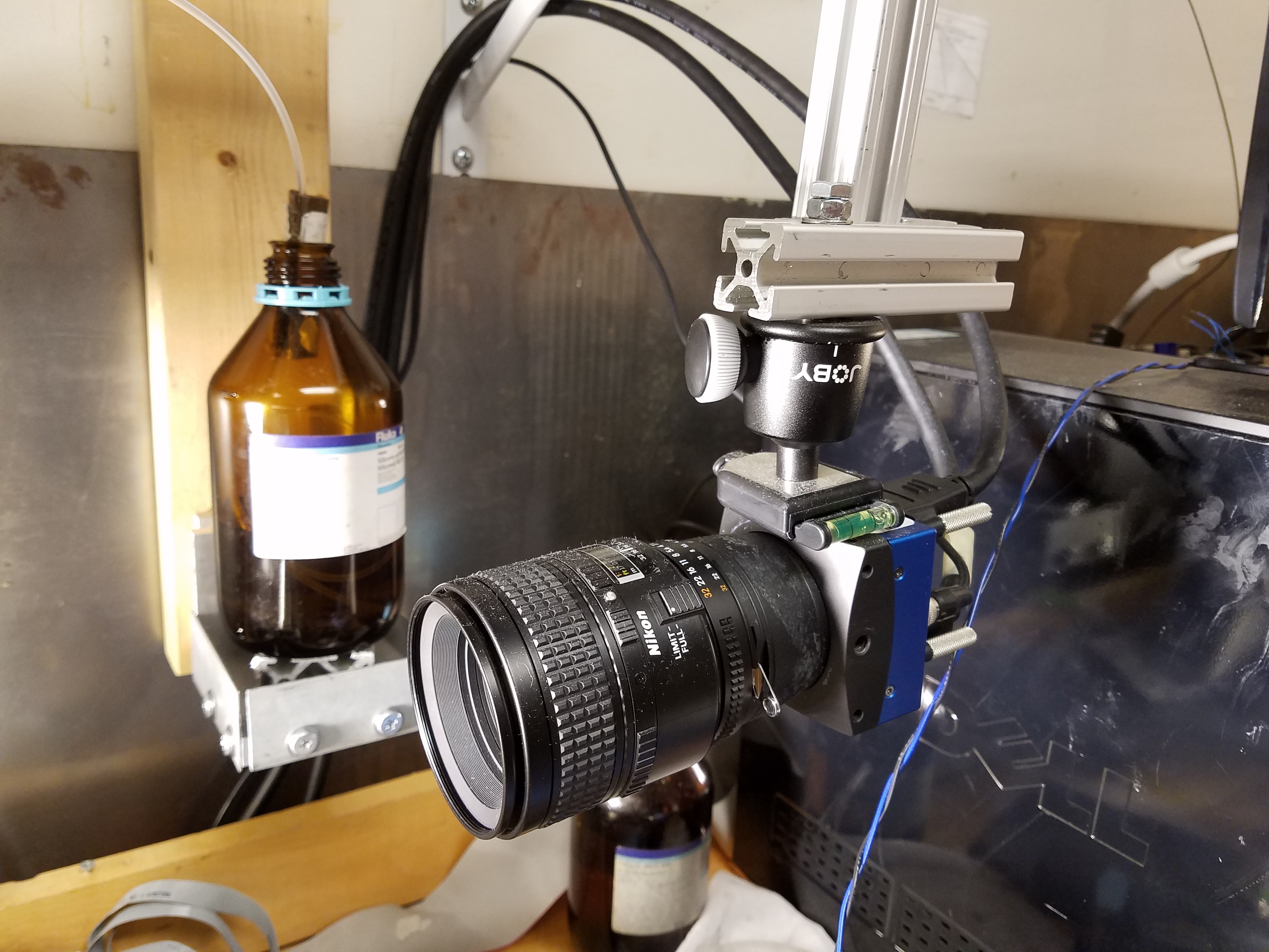
DOD (Droplet On Demand) Generator
This is a device used to generate a single droplet of fluid. The device is a small fluid reservoir capped with a piezoelectric actuator. It is filled from a gravity siphoned reservoir, and narrows to a 1 mm diameter nozzle at the bottom. By adjusting the relative heights of the generator and reservoir, a meniscus is created in the nozzle. When the piezo is fired for a specific pulse length, the pressure wave forces a small amount of fluid out of the nozzle, creating a single droplet of constant volume and velocity. It is attached to a 2 degree of freedom gantry for positioning.
-
DOD generator was inspired and partially modeled from Bush’s paper “A low-cost, precis piezoelectric droplet-on-demand generator”
-
Nozzle was purchased from SeeMeCNC as a 3D printer nozzle; the outside diameter of the nozzle was machined to 1.0 mm
-
DOD generator produces a droplet through the piezoelectric disk creating a pressure wave when flexed (positive voltage applied). This pressure wave travels down the generator chamber and produces a droplet of roughly 1.0 mm.
- Characteristics of the drop size are voltage applied (~30V) and pulse time (~1000 us) for piezoelectric pulse, as well as the fluid height difference between the meniscus at the nozzle and the top of the fluid reservoir.
-
The meniscus formed at the nozzle tip should be close to the critical location.
-
If the meniscus is too far down the nozzle, the meniscus will slowly create a drop from wetting the outside of the nozzle.
-
If the meniscus is too far up the nozzle, the piezoelectric pulse will not be enough to create a droplet.
-
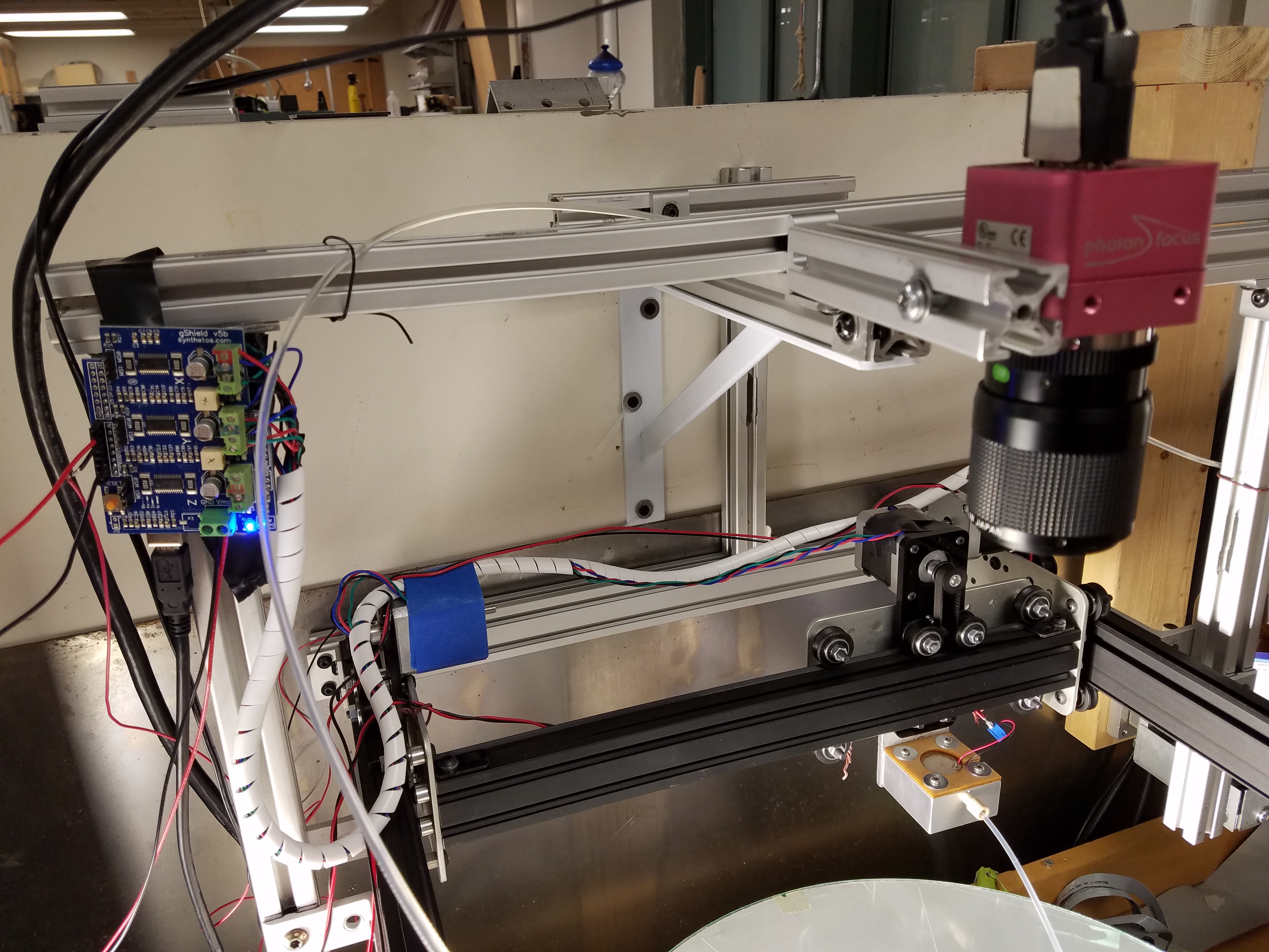
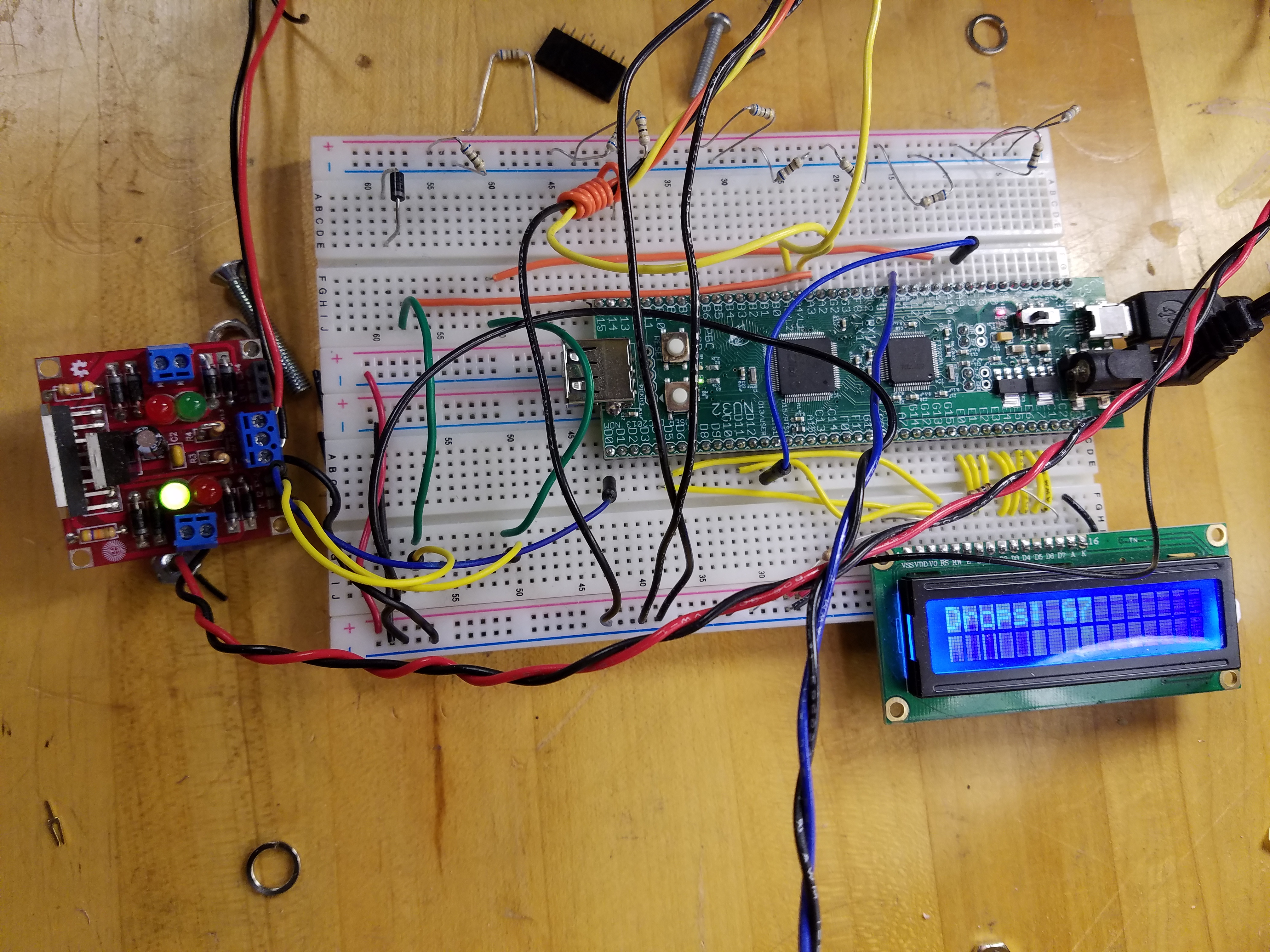
DOD Gantry (Arduino UNO)
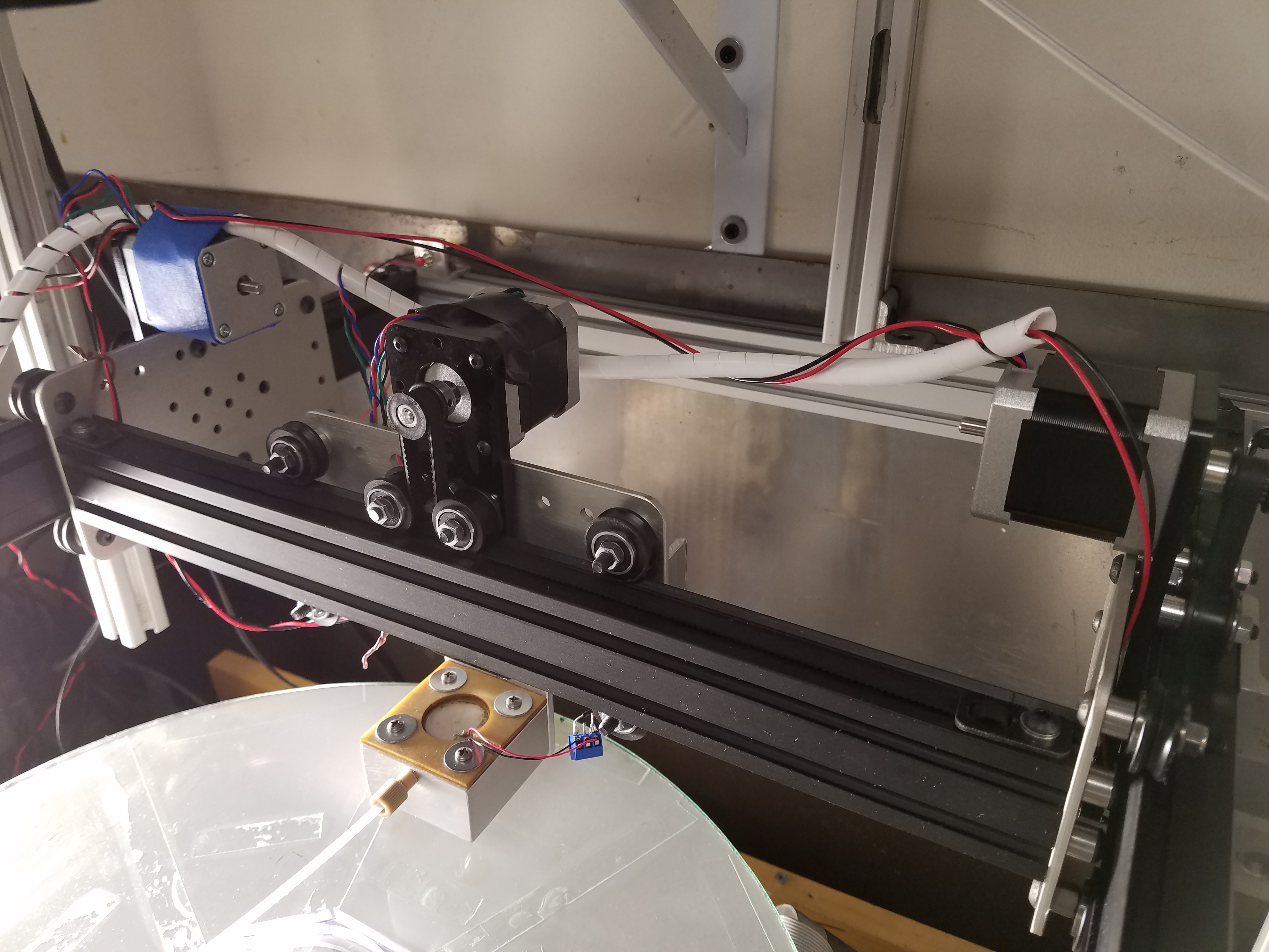
The gantry moves the DOD to a specified location. This way multiple droplets can be created and by placing them in different areas of a vibration field, more complex control of droplets is possible.
-
Built from Inventables components
-
Controlled by Arduino UNO microcontroller with TinyG motion control board running GRBL
-
Controlled by sending single lines of Gcode over a serial connection
-
Performs homing cycle on startup
-
Default location is the center of PPOD, called (0, 0)
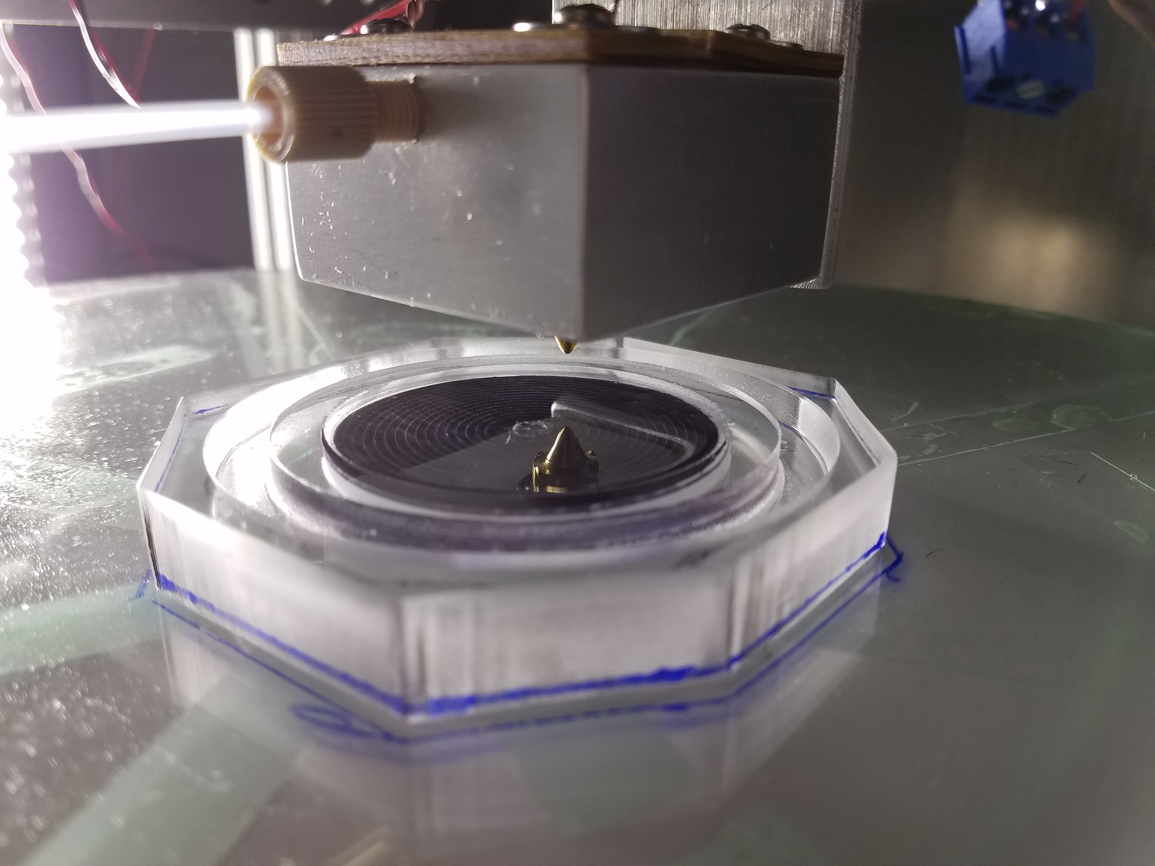
Fluid bath
To bounce droplets on the PPOD consistently, a thin fluid layer needed to be attached to the table. A fluid bath was machined and attached to the PPOD for this purpose. Two versions wereused; one used a circular pocket to hold a small volume of fluid, the other used a thin PTFE membrane to hold a thin layer of fluid on a smooth surface.
-
2” diameter circular fluid layer for manipulating droplets
-
0.5” thick acrylic with 0.25” embedded neodymium magnet to anchor it to PPOD table
-
0.2” deep ring channel around bath to collect excess fluid
-
Pocket version uses a 0.5mm depression to hold fluid
-
Membrain version uses a very thin PTFE membrane to hold fluid like a sponge
Future Work
Possible future work on this project
-
Improvement of droplet tracking using computer vision and machine learning
- Learning what droplets look like to improve tracking when droplets deform during impact
-
Live droplet tracking
- Conditional, not useful or possible in every experiment
-
Dust Management
- Surface contamination was a consistent problem when using very thin fluid surfaces
-
Surface Characterization
-
Work was done with PTFE membranes and shallow fluid baths
-
More thorough characterization of these surfaces could improve results
-
-
Variable droplet size
-
Implementing switching fields during droplet manipulation
- Quickly changing the PPOD frequency while droplets continue bouncing could provide more control methods
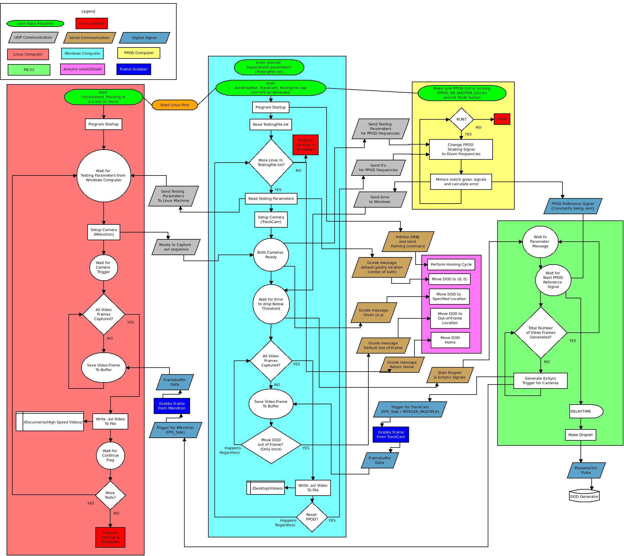
Diagrams
Configuration of system showing all relevant systems and their communications
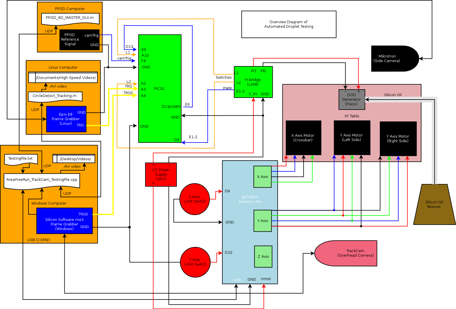
Flowchart of automated droplet testing