
Baxter-Mounted Jamming Gripper
March 19, 2016
Demo
Overview
This project involved designing, developing, and prototyping a more versatile gripper that would be compatible with Rethink Robotics’ Baxter Robot. This project was inspired by my previous work on the Baxter Pick and Place project. A Universal Jamming Gripper design was chosen because it correct a problem encountered during that project; grasping failing due to object orientation.
Universal Jamming Gripper
This gripper design was created by a team from The University of Chicago and Cornell University in 2011. Here is their paper, used for reference in this project. A jamming gripper is a simple design that operates on the jamming effect of particulates. It consists of a flexible membrane partially filled with a granular material connected to a pneumatic system. When air is vacuumed out of the membrane, the filler material jams together, locking into a rigid solid shape. If this happens when the membrane is deformed around an object, the gripper holds onto the object until the membrane is re-pressurized. Positive pressure is used to re-fill the balloon to reset the shape for gripping again. This design has already proven to be effective at grasping irregularly shaped or oriented objects, but currently no design exist specifically for use on the Baxter robot.
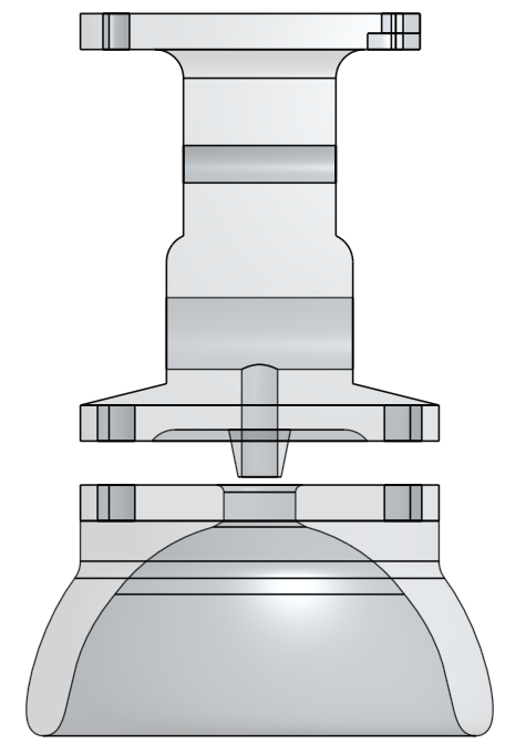
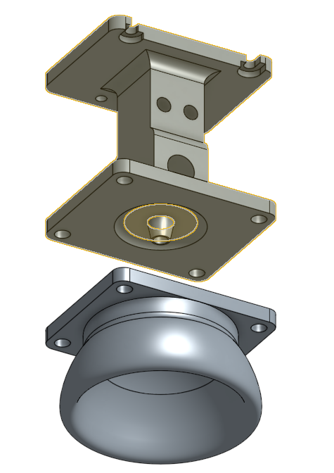
Design
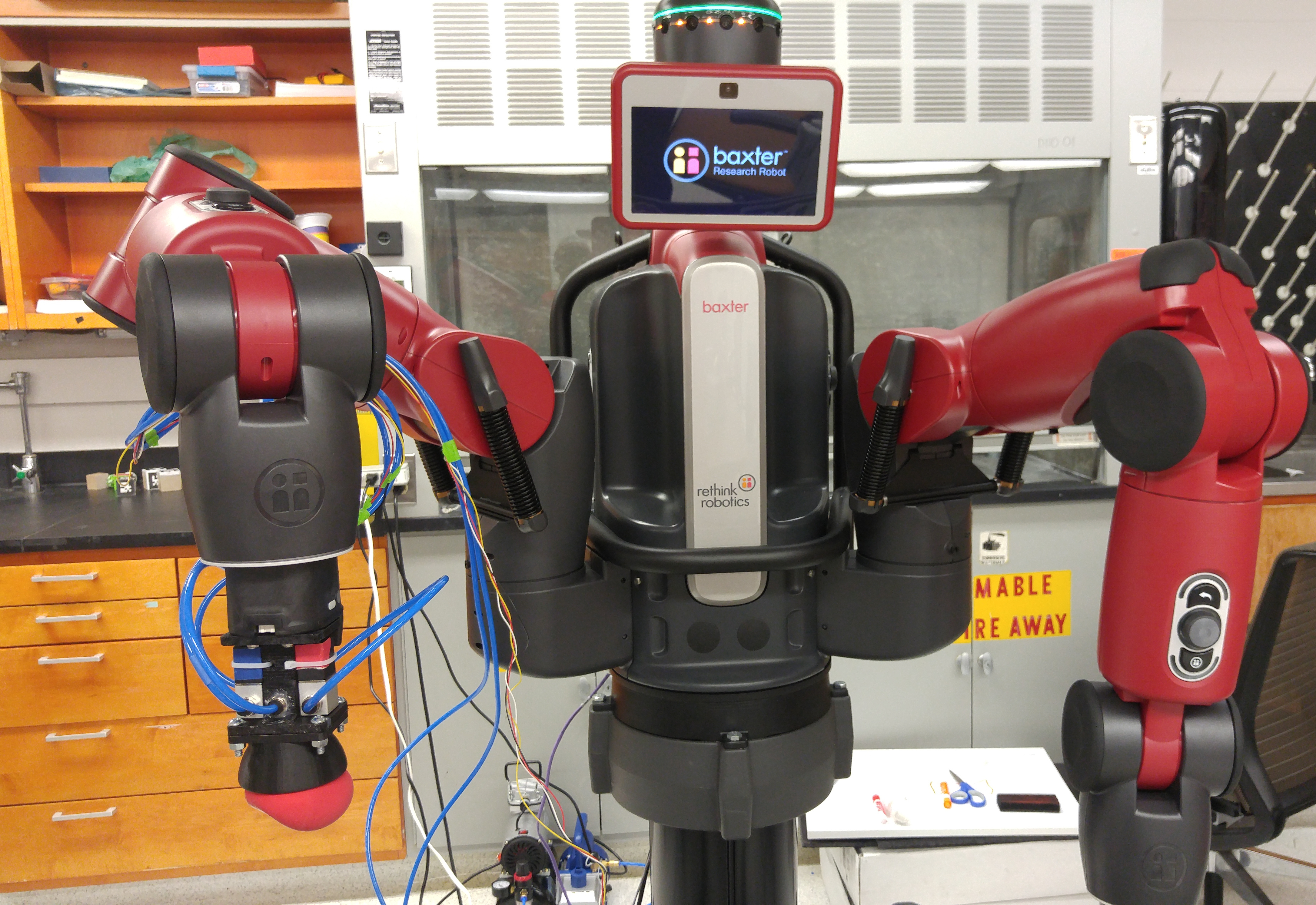
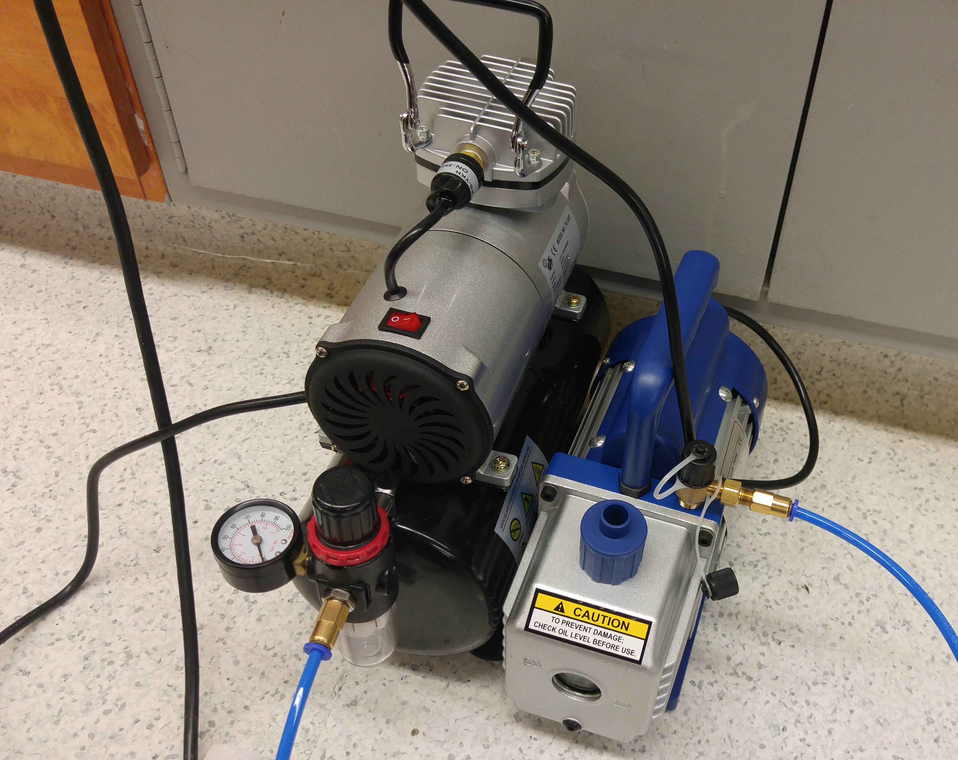
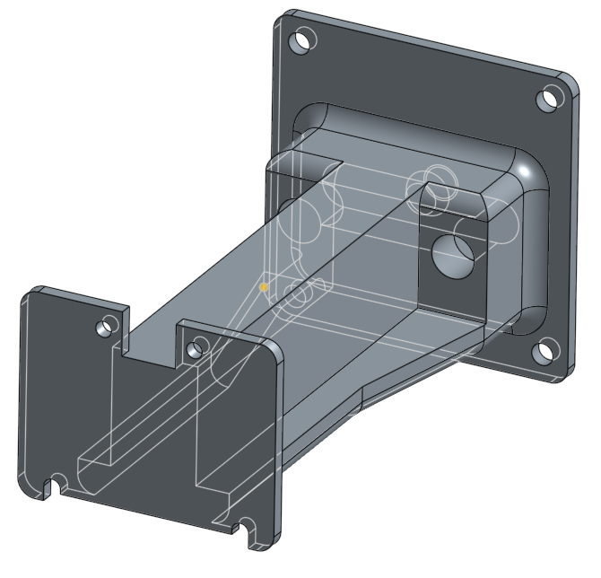
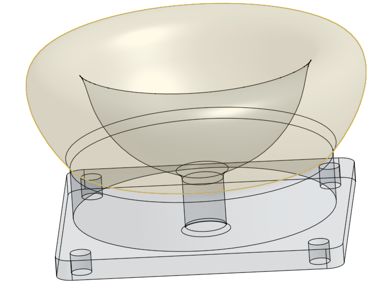
The current working design uses a latex balloon filled with ground coffee for the gripper. It uses a 5 Pa, 3 CFM vacuum pump to supply negative air pressure, and a ⅕ hp air compressor for positive pressure. The pneumatics are plumbed with 4mm diameter tubing, and are controlled electronically by solenoid valves. The gripper was designed in CAD software and manufactured with a 3D printer. It is in two pieces; the main body which holds the solenoids and an air cavity for feeding the positive and negative pressure tubes into the balloon, and an end cup which attaches to the body and holds the balloon and filter in place. The gripper attaches to Baxter with a mounting plate designed to interface with Baxter’s cuff. This was made possible by drawings of Baxter’s arm provided by Rethink Robotics.
Prototyping
The majority of iterating on this design was done through rapid prototyping. Four major prototypes were created, but minor variation of each were also tested.
1 Proof of Concept
This prototype was a quick test of the concept. It was created using a latex balloon filled with ground coffee attached to a vacuum cleaner using a funnel and a dishrag. It was cheap, fast, and had many problems, but it proved the idea was viable as it could grasp and pick up odd-shaped pens and pencils.
2 3D Printing Test
All of the further designs were prototyped using a 3D Printer in ABS plastic. To test the viability of printing an air chamber directly in the part, a small test section of the CAD design was printed. This section contained the air cavity needed to join the positive and negative airflow to the balloon. It proved to be mostly airtight once it was fitted with adapters for the 4mm tubing, although these adapters did need to be sealed with glue.
A preliminary design for an end cup was also printed to test the shape and strength of the material. This design turned out to be bigger than was necessary as the material proved to be quite strong.
3 Full Pump Test
This was a full print of the gripper design after it was adjusted to be more compact. The end cap fitted the balloon perfectly, and the air cavity was fairly airtight. When hooked up to the pumps and solenoid valves the gripper could pick up larger objects such as rolls of masking tape and plastic widgets. It was found that partially inflating the balloon prior to pick-up improved the success rate dramatically.
The only problem was with the printing orientation. Because 3D printers operate by laying down thin layers of plastic and building them up, changing the orientation affects the internal structure of the part. This was a problem because when the gripper was attached to Baxter, the layers in the center of section de-laminated and failed at the stress point above the bottom mounting plate.
4 Working Design
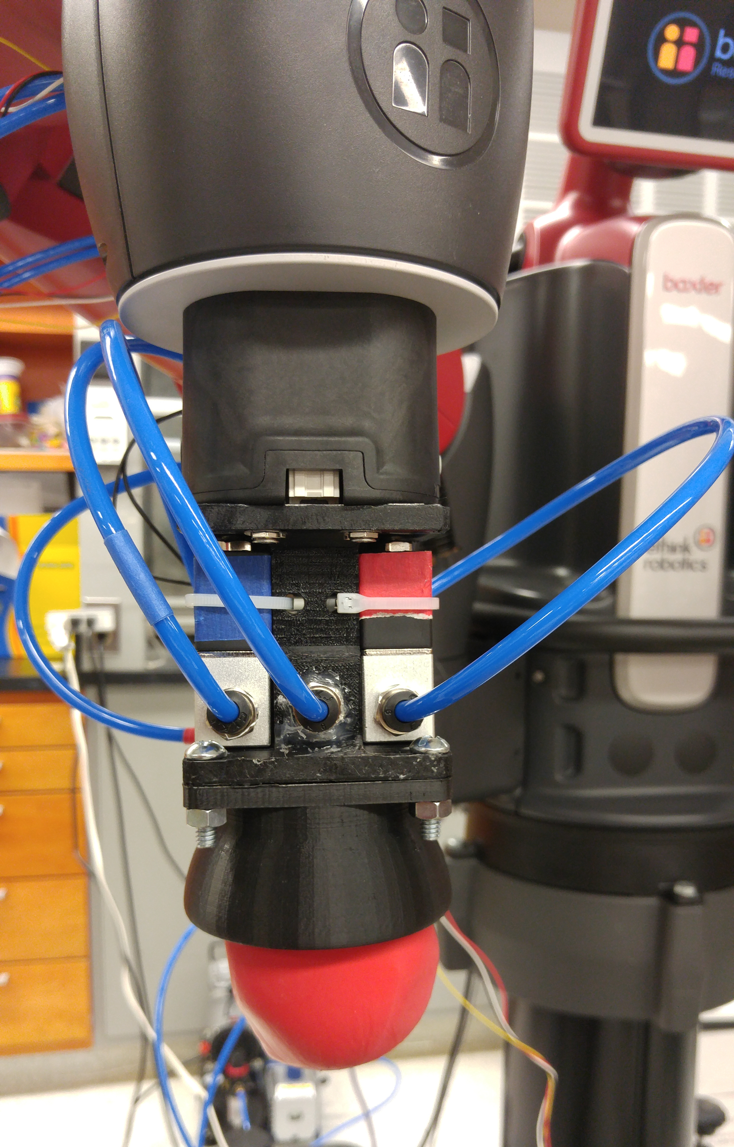
This is the version demonstrated in the video. It is mostly the same model used in 3, but it was printed in a different orientation to strengthen the connection between the mounting plate and the center. This design proved more airtight than the last, and as such could grasp larger and heavier objects such as the blocks used in the Pick and Place project.
Printing still proved difficult because in this new orientation, the bottom of the mounting plate tended to crack and fail during printing. Adjusting the plate thickness and the 3D printing settings eventually corrected this problem after a few failed trials.
Electronic Control
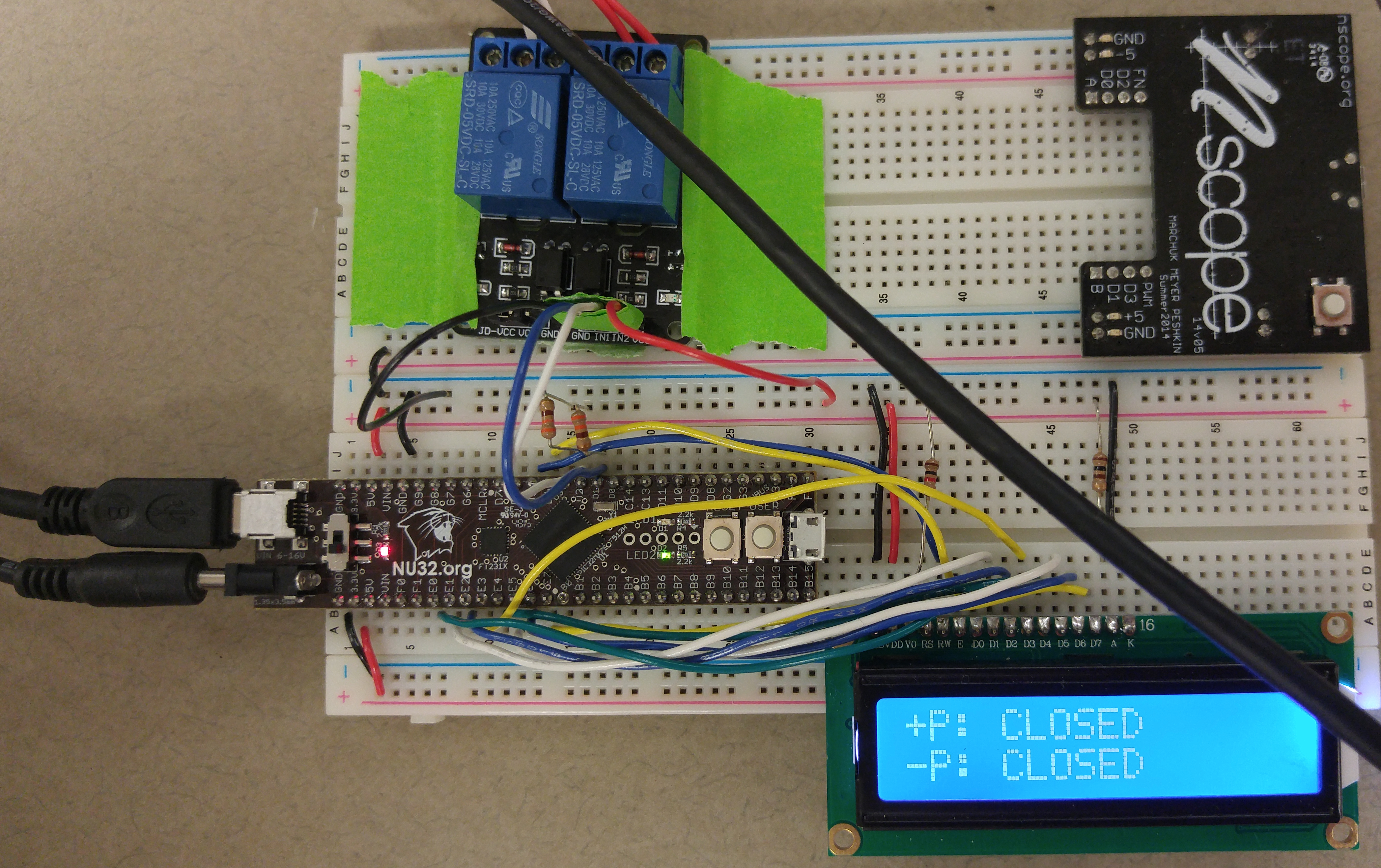
The solenoids are switched electronically using a relay. A 2 channel, 10A relay was used to accommodate the relatively large voltage and current necessary to operate the solenoids.
For interfacing with Baxter, the relay must be controlled by a computer running ROS. This was accomplished with a PIC32 microcontroller. The PIC32 communicates with the ROS nodes running Baxter through a UART connection and uses two digital I/O pins to switch the relay. An LCD screen is used to display the state of each solenoid. The interface was accomplished with functions written in Python.
Files
Github
Code used in this project can be found at this project can be found in the Pick and Place repo under the jamming branch. Here is the Github repo for the project
OnShape
All the CAD files were generated in OnShape and can be found at this link.